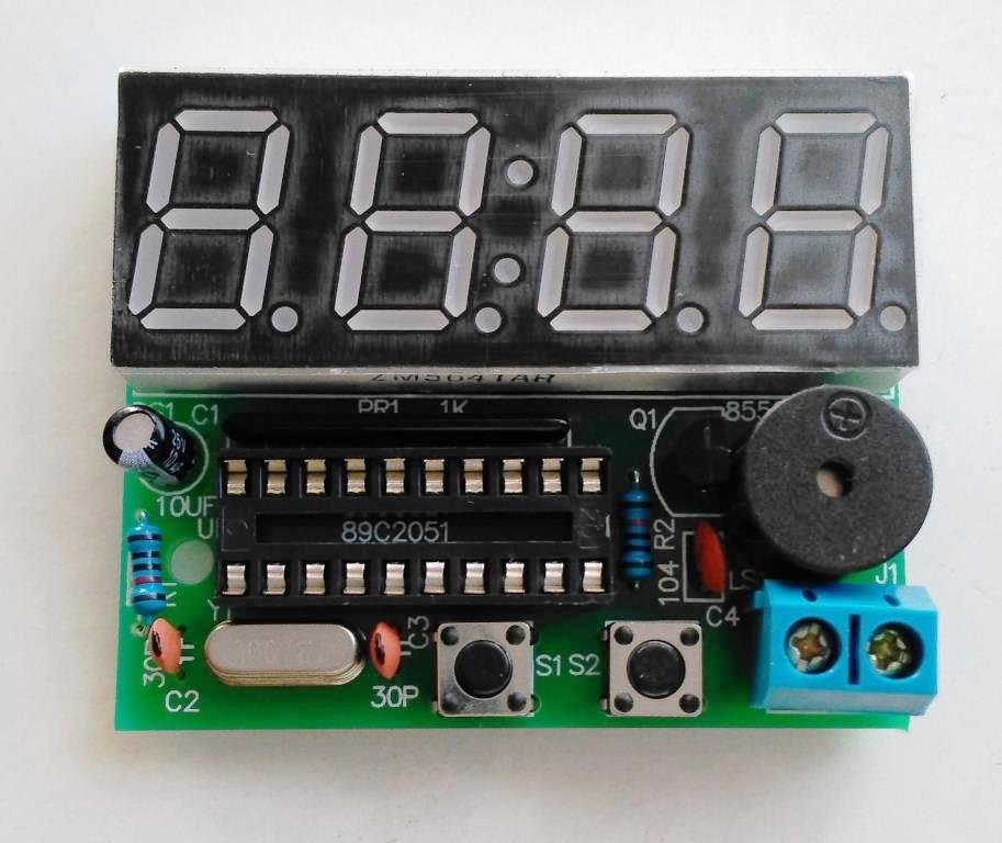
How to assemble DIY digital clock kit Circuit Diagram This is the circuit diagram of the digital clock using 8051 microcontroller. As we can see the microcontroller is connected to three 7 segment display with distinct ports not multiplexed and the last hour digit is only connected to a pin as it only shows 1.. LED and buzzer are self explanatory according to the code.. 1 of the LED is for AM and I have connected another LED not shown in the
How to make seven segment digital clock & How to coding or programing in PIC Microcontroller IC or Chip. Get Circuit Diagram of Simple Digital Clock Using PI Circuit diagram of digital clock ds1307 using pic mirocontroller is given below. DS1307 real time clock is interfaced with PIC16F877A microcontroller. Instructions for interfacing real time clocl ds130 is given. 3 volt battery is used as back up which is used in case of main power supply faliure.PIC16F877A microcontroller fetch time and date

Digital clock with 8051(89c51,89c52) microcontroller 16x2 lcd and 4x4 ... Circuit Diagram
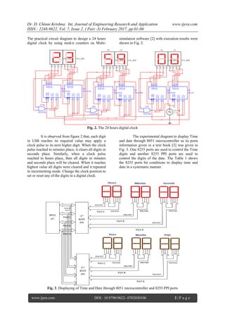
The digital clock circuit uses the 50-60hz oscillation of AC power.Most digital alarm clocks display the hour of the day in the form of 12 hours or 24 hours with an indication of AM or PM. Most digital alarm clocks use LCD display, seven segment display or VFD. Digital clocks run with mains electricity and must be reset the time when the power

Real time clock (RTC) is widely used in many application to provide accurate time. This article explains the making of a simple digital clock using RTC DS 12C887 and 8051 microcontroller (AT89C51). The output is displayed on an LCD. This clock also has a provision of setting time at any instant. The clock uses the concept of our earlier articles of interfacing RTC DS12C887 with microcontroller
digital clock ds1307 circuit & project using pic microcontroller Circuit Diagram
Usually digital RTC(real time clocks) are interfaced with microcontrollers to make a digital clock. But i utilized the internal timers of 89c51 microcontroller to generate a precise time for making a clock with 8051 microcontroller. 16×2 lcd is interfaced with 8051 microcontroller to display time on lcd. Time in minutes, hours and seconds will

For this clock, we can set the time at any instant. Here, the clock can work in either 24 hour mode or 12 hour mode and the RTC chip is configured by programming 8051 controller. I will demonstrate two circuits of Digital Clocks using 8051 Microcontroller: one uses the RTC DS12C887 and the other uses the RTC DS1307. Circuit Principle
