Arduino Controlled Light Dimmer Instructables Circuit Diagram This is a circuit that tells the Arduino (or another micro controller) when the sinus-wave goes through zero and therefore gives a defined point on that sinus wave. Step 6: Arduino Controlled Light Dimmer: the Software III. The code below uses the timer function rather than a delay and has been confirmed to work on the Leonardo as well

Light dimmer dims light and glow light with defined manner.Components:1. Arduino Uno/ Nano/ Mega2. Switching Transistor: BC548/BC547/2N2222A or any NPN trans
How to Create a dimmer with Arduino: dimmable LED Circuit Diagram
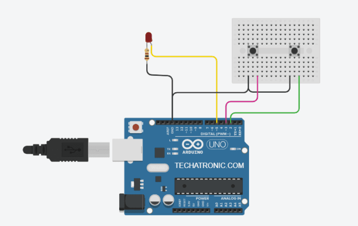
Use an Arduino to make a dimmer and control the brightness of a lamp. Network Sites: Latest; Forums; Education; Tools; Videos; Datasheet; Circuit for the Arduino Lamp Dimmer. Lamp Dimmer Circuit. The figure above explains the positioning of the different electrical components in the circuit. Follow the circuit diagram to solder your dot board. Hey guys, today we are going to learn how to make a light dimmer circuit using an Arduino board. There are two pushbuttons in this circuit, one is for increasing the brightness of the LED and the other one is for decreasing the brightness. So basically you can control the brightness level of any LED by using this project.
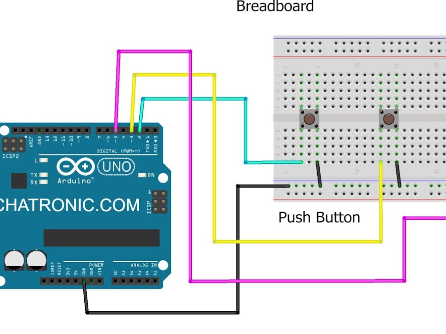
Take two push buttons and place them on the breadboard in such a way that the pair of interconnected pins are in a verticle position. Join the one pin of the first pushbutton with the negative rail of the breadboard and the other pin with the digital-2 pin of the Arduino.

How to Make an Arduino Circuit Diagram
To make an Arduino LED Dimmer project, you need to use a PWM output pin and an analog input pin (for the potentiometer) 1- Set an IO pin as an output pin using the pinMode function. 2- Continuously read the analog input pin for the potentiometer 3- Map the 10-Bit ADC reading to the range of the 8-Bit PWM's duty cycle and write the value using

Arduino light dimmer circuit: Project circuit schematic diagram is shown below. All grounded terminals are connected together. In this project I used the LM393 (dual comparator IC) for the zero crossing detection, the LM339 quad comparator IC also can be used. An optocoupler can be used for the same purpose( zero crossing detection) but I think
